INTRODUCTION
Eugene Carlo L. Roces
- Gender: Male
- Astrological Sign: Sagittarius
- Industry: Technology
- Location: Lucena,City : Philippines
About Me
simple ...!Interests
Favorite Movies
Favorite Music
Favorite Books
- ........
My Favorite Topic
My Favorite topic is the semifinal topic because networking is important to us by communicate others by using the computer technology to chat and see them live using the web cam...and the importance of database in the business.BASICON
Prelim Topic
Abacus

. The woodcut shows Arithmetica instructing an algorist and an abacist (inaccurately represented as Boethius and Pythagoras). There was keen competition between the two from the introduction of the Algebra into Europe in the 12th century until its triumph in the 16th.[1]
Charles Babbage
| Charles Babbage | |
|---|---|
 The Illustrated London News (4 November 1871).[1] | |
| Born | 26 December 1791 London, England |
| Died | 18 October 1871 (aged 79) Marylebone, London, England |
| Nationality | English |
| Fields | Mathematics, analytical philosophy, computer science |
| Institutions | Trinity College, Cambridge |
| Alma mater | Peterhouse, Cambridge |
| Known for | Mathematics, computing |
| Signature | |
The Five Generations of Computers
First Generation (1940-1956) Vacuum Tubes
The first computers used vacuum tubes for circuitry and magnetic drums for memory, and were often enormous, taking up entire rooms. They were very expensive to operate and in addition to using a great deal of electricity, generated a lot of heat, which was often the cause of malfunctions.
First generation computers relied on machine language, the lowest-level programming language understood by computers, to perform operations, and they could only solve one problem at a time. Input was based on punched cards and paper tape, and output was displayed on printouts.
The UNIVAC and ENIAC computers are examples of first-generation computing devices. The UNIVAC was the first commercial computer delivered to a business client, the U.S. Census Bureau in 1951.

Second Generation (1956-1963) Transistors
Transistors replaced vacuum tubes and ushered in the second generation of computers. The transistor was invented in 1947 but did not see widespread use in computers until the late 1950s. The transistor was far superior to the vacuum tube, allowing computers to become smaller, faster, cheaper, more energy-efficient and more reliable than their first-generation predecessors. Though the transistor still generated a great deal of heat that subjected the computer to damage, it was a vast improvement over the vacuum tube. Second-generation computers still relied on punched cards for input and printouts for output.
Second-generation computers moved from cryptic binary machine language to symbolic, or assembly, languages, which allowed programmers to specify instructions in words. High-level programming languages were also being developed at this time, such as early versions of COBOL and FORTRAN. These were also the first computers that stored their instructions in their memory, which moved from a magnetic drum to magnetic core technology.
The first computers of this generation were developed for the atomic energy industry.
Third Generation (1964-1971) Integrated Circuits
The development of the integrated circuit was the hallmark of the third generation of computers. Transistors were miniaturized and placed on silicon chips, called semiconductors, which drastically increased the speed and efficiency of computers.
Instead of punched cards and printouts, users interacted with third generation computers through keyboards and monitors and interfaced with an operating system, which allowed the device to run many different applications at one time with a central program that monitored the memory. Computers for the first time became accessible to a mass audience because they were smaller and cheaper than their predecessors.

Fourth Generation (1971-Present) Microprocessors
The microprocessor brought the fourth generation of computers, as thousands of integrated circuits were built onto a single silicon chip. What in the first generation filled an entire room could now fit in the palm of the hand. The Intel 4004 chip, developed in 1971, located all the components of the computer—from the central processing unit and memory to input/output controls—on a single chip.
In 1981 IBM introduced its first computer for the home user, and in 1984 Apple introduced the Macintosh. Microprocessors also moved out of the realm of desktop computers and into many areas of life as more and more everyday products began to use microprocessors.
As these small computers became more powerful, they could be linked together to form networks, which eventually led to the development of the Internet. Fourth generation computers also saw the development of GUIs, the mouse and handheld devices.


Fifth Generation (Present and Beyond) Artificial Intelligence
Fifth generation computing devices, based on artificial intelligence, are still in development, though there are some applications, such as voice recognition, that are being used today. The use of parallel processing and superconductors is helping to make artificial intelligence a reality. Quantum computation and molecular and nanotechnology will radically change the face of computers in years to come. The goal of fifth-generation computing is to develop devices that respond to natural language input and are capable of learning and self-organization.

Analytical engine
 The analytical engine, an important step in the history of computers, was the design of a mechanical general-purpose computer by English mathematician Charles Babbage. In its logical design the machine was essentially modern, anticipating the first completed general-purpose computers by about 100 years. It was first described in 1837. Babbage continued to refine the design until his death in 1871. Because of the complexity of the machine, the lack of project management science, the expense of its construction, and the difficulty of assessing its value by Parliament relative to other projects being lobbied for, the engine was never built.
Some have said that the technological limitations of the time were a further obstacle to the construction of the machine, but this has been refuted by the "partial" construction of one of Babbage's machines by his son Henry, and now by the construction of one of his simpler designs by the British Science Museum.[2] Indications are today that the machine could have been built successfully with the technology of the era if funding and political support had been stronger.
Difference engine
The Difference Engine was an automatic, mechanical calculator designed to tabulate polynomial functions. Both logarithmic and trigonometric functions can be approximated by polynomials, so a difference engine can compute many useful sets of numbers.
Midterm Topic
The Motherboard
The main goal is to connect all the hardware together like hard drives, memory modules, CPU, etc...
A computer mother board is made of several parts, and each one has a hardware that can be connected to it. On the right, the image is showing a modern motherboard with all its parts.
If you click on the link under the image, you will find a larger image with the motherboard parts name.
Learning about your motherboard parts help to understand how upgrade able it is.
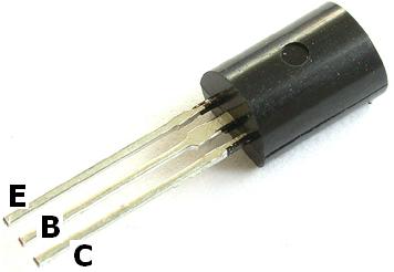
BY ITS PARTS
The Processor Socket
Sockets are the home for your Central Processor Unit (CPU). Several types of socket exist, but only 2 of them are really used, and both of them are used by Intel and AMD. The Pin Grid Array (PGA) and the Land Grid Array (LGA).
CPU Socket
I am discussing this subject in more details in the CPU socket type guide.
To know the form of CPU your motherboard can use and the range of powers and FSBs, look in your motherboard's book. The book that comes with your motherboard has a chart about it in the socket or CPU chapter. That information will give you an idea to how far you can upgrade your CPU.
- CPU Socket Specifications
- How to install cpu step by step
Memory Slots
Memory slots also call memory banks are for Random Access Memory modules (RAM). Each memory bank can receives a RAM module designed for a specific pc mother board. Ranging from 2 to 4 banks, you will encounter single and dual-channel technologies.
Memory Banks
To get the most of it, you need to fill 2 banks with the same module types, from the same manufacturer with exactly the same memory amounts.
If you want 1GB of memory, you need to use 2 512MB modules from the same manufacturer with the same technology type. This way, motherboards use the modules strength to its full capacity. Otherwise it may not work at all.
Like the socket, to find out the type, the manufacturer and the total MB or GB quantity you can use, take a look in your motherboard's book. You should be able to find everything you need.
- Introduction to Desktop Computer Memory
- How to Install Computer Memory step by step
Main Power Connector And The 4 Pins Connector
The main power connector is uses to get the electric energy from the power supply which the motherboard require to function properly.24 Pins Main Power Connector
Not all power supplies have the 2 types, but it is possible to work around the problem if you run into an incompatibility situation. Which will be discussed in a future power supply guide about how to install it and where to plug the connectors.
- Introduction to Computer Power Supplies
IDE, ATA And S-ATA Interface Connectors
Many interface standards have been created throughout the years, maybe too many for discussing about all of them. I will then talk about the ATA and the S-ATA only as the IDE is the same thing as the ATA, only the name has changed. Also I will be brief because it is more a hard drive topic than anything else.
IDE/ATA And SATA Interface
Modern computer mother boards have the new interface called Serial Advance Technology Attachment (S-ATA). It is faster than the ATA and only 1 device can be attached to it. The wire is thinner than his predecessor and surely help at the cooling process inside the computer case.
I cover the topic in more details in the What Is SATA Interface guide.
Floppy Drive Connector
Floppy Drive Connector
32 bit PCI Slots, AGP And PCIe
32 bit slots Peripheral Component Interconnect (PCI) are used to install sound cards, graphic cards, Ethernet cards and modems.
PCI, AGP or PCIe Ports
PCIe standard is even better than AGP standard, and mostly the only one used right now. Some like to say, PCIe is a AGP standard at x16 and it is the #1 choice for gaming machines right now.
More motherboard content will be written on it, especially for graphic cards.
Back Panel Connectors

Back Panel Connectors
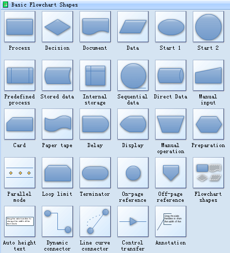
Basic Flowchart Symbols
- Start and end symbols, represented as lozenges, ovals or rounded rectangles, usually containing the word "Start" or "End", or another phrase signaling the start or end of a process, such as "submit enquiry" or "receive product".
- Arrows, showing what's called "flow of control" in computer science. An arrow coming from one symbol and ending at another symbol signifies flow passes to the symbol the arrow points to.
- Processing steps, represented as rectangles. Examples: "Add 1 to X"; "replace identified part"; "save changes" or similar.
- Input/Output, represented as a parallelogram. Examples: Get X from the user; display X.
- Conditional (or decision), represented as a diamond (rhombus). These typically contain a Yes/No question or True/False test. This symbol is unique in that it has two arrows coming out of it, usually from the bottom point and right point, one corresponding to Yes or True, and one corresponding to No or False. The arrows should always be labeled. More than two arrows can be used, but this is normally a clear indicator that a complex decision is being taken, in which case it may need to be broken-down further, or replaced with the "pre-defined process" symbol.
Standard Flowchart Symbols
Flowcharts use special shapes to represent different types of actions or steps in a process. Lines and arrows show the sequence of these steps, and the relationships between them.Free Download Flowchart Software and View All Vector Symbols
ASCII
From Wikipedia, the free encyclopedia
Not to be confused with Windows-1252, also known as "ANSI".
This article is about the character encoding. For other uses, see ASCII (disambiguation).

The 95 ASCII graphic characters are numbered from 0x20 to 0x7E (32 to 126 decimal). The space character was initially considered to be a non-printing character.[1]
US-ASCII is the Internet Assigned Numbers Authority (IANA) preferred charset name for ASCII.
Historically, ASCII developed from telegraphic codes. Its first commercial use was as a seven-bit teleprinter code promoted by Bell data services. Work on ASCII formally began on October 6, 1960, with the first meeting of the American Standards Association's (ASA) X3.2 subcommittee. The first edition of the standard was published during 1963,[3][4] a major revision during 1967,[5] and the most recent update during 1986.[6] Compared to earlier telegraph codes, the proposed Bell code and ASCII were both ordered for more convenient sorting (i.e., alphabetization) of lists, and added features for devices other than teleprinters.
ASCII includes definitions for 128 characters: 33 are non-printing control characters (now mostly obsolete) that affect how text and space is processed;[7] 94 are printable characters, and the space is considered an invisible graphic.[8] The most commonly used character encoding on the World Wide Web was US-ASCII[9] until December 2007, when it was surpassed by UTF-8.
Ethernet hub
An Ethernet hub, active hub, network hub, repeater hub or hub is a device for connecting multiple twisted pair or fiber optic Ethernet devices together and making them act as a single network segment. Hubs work at the physical layer (layer 1) of the OSI model. The device is a form of multiport repeater. Repeater hubs also participate in collision detection, forwarding a jam signal to all ports if it detects a collision.
Hubs also often come with a BNC and/or Attachment Unit Interface (AUI) connector to allow connection to legacy 10BASE2 or 10BASE5 network segments. The availability of low-priced network switches has largely rendered hubs obsolete but they are still seen in older installations and more specialized applications.
Programming language
A programming language is an artificial language designed to express computations that can be performed by a machine, particularly a computer. Programming languages can be used to create programs that control the behavior of a machine, to express algorithms precisely, or as a mode of human communication.
Many programming languages have some form of written specification of their syntax (form) and semantics (meaning). Some languages are defined by a specification document. For example, the C programming language is specified by an ISO Standard. Other languages, such as Perl, have a dominant implementation that is used as a reference.
SemiFinal Topic
NETWORKING

Network topology
Network topology is the layout pattern of interconnections of the various elements (links, nodes, etc.) of a computer network.[1][2] Network topologies may be physical or logical. Physical topology means the physical design of a network including the devices, location and cable installation. Logical topology refers to how data is actually transferred in a network as opposed to its physical design..

Basic topology types
The study of network topology recognizes seven basic topologies:- Single Node Topology
- Bus topology
- Star topology
- Ring topology
- Tree topology
- Mesh topology
- Hybrid topology
Point-to-point
The simplest topology is a permanent link between two endpoints (the line in the illustration above). Switched point-to-point topologies are the basic model of conventional telephony. The value of a permanent point-to-point network is the value of guaranteed, or nearly so, communications between the two endpoints. The value of an on-demand point-to-point connection is proportional to the number of potential pairs of subscribers, and has been expressed as Metcalfe's Law.Bus
Main article: Bus network

- In local area networks where bus topology is used, each machine is connected to a single cable. Each computer or server is connected to the single bus cable through some kind of connector. A terminator is required at each end of the bus cable to prevent the signal from bouncing back and forth on the bus cable. A signal from the source travels in both directions to all machines connected on the bus cable until it finds the MAC address or IP address on the network that is the intended recipient. If the machine address does not match the intended address for the data, the machine ignores the data. Alternatively, if the data does match the machine address, the data is accepted. Since the bus topology consists of only one wire, it is rather inexpensive to implement when compared to other topologies. However, the low cost of implementing the technology is offset by the high cost of managing the network. Additionally, since only one cable is utilized, it can be the single point of failure. If the network cable breaks, the entire network will be down.
Star
Main article: Star network

Mesh
Main article: Mesh networking
The value of fully meshed networks is proportional to the exponent of the number of subscribers, assuming that communicating groups of any two endpoints, up to and including all the endpoints, is approximated by Reed's Law.

- Partially connected
-
- The type of network topology in which some of the nodes of the network are connected to more than one other node in the network with a point-to-point link – this makes it possible to take advantage of some of the redundancy that is provided by a physical fully connected mesh topology without the expense and complexity required for a connection between every node in the network.
Tree

The type of network topology in which a central 'root' node (the top level of the hierarchy) is connected to one or more other nodes that are one level lower in the hierarchy (i.e., the second level) with a point-to-point link between each of the second level nodes and the top level central 'root' node, while each of the second level nodes that are connected to the top level central 'root' node will also have one or more other nodes that are one level lower in the hierarchy (i.e., the third level) connected to it, also with a point-to-point link, the top level central 'root' node being the only node that has no other node above it in the hierarchy (The hierarchy of the tree is symmetrical.) Each node in the network having a specific fixed number, of nodes connected to it at the next lower level in the hierarchy, the number, being referred to as the 'branching factor' of the hierarchical tree.This tree has individual peripheral nodes.
Database
Database management systems
Main article: Database management system
A database management system (DBMS) consists of software that operates databases, providing storage, access, security, backup and other facilities. Database management systems can be categorized according to the database model that they support, such as relational or XML, the type(s) of computer they support, such as a server cluster or a mobile phone, the query language(s) that access the database, such as SQL or XQuery, performance trade-offs, such as maximum scale or maximum speed or others. Some DBMS cover more than one entry in these categories, e.g., supporting multiple query languages.Examples of some commonly used DBMS are MySQL, PostgreSQL, Microsoft Access, SQL Server, FileMaker,Oracle, RDBMS, dBASE, Clipper,FoxPro,etc. Almost every database software comes with an Open Database Connectivity (ODBC) driver that allows the database to integrate with other databases.Components of DBMS
Most DBMS as of 2009[update] implement a relational model.[2] Other DBMS systems, such as Object DBMS, offer specific features for more specialized requirements. Their components are similar, but not identical.RDBMS components
- Sublanguages— Relational DBMS (RDBMS) include Data Definition Language (DDL) for defining the structure of the database, Data Control Language (DCL) for defining security/access controls, and Data Manipulation Language (DML) for querying and updating data.
- Interface drivers—These drivers are code libraries that provide methods to prepare statements, execute statements, fetch results, etc. Examples include ODBC, JDBC, MySQL/PHP, FireBird/Python.
- SQL engine—This component interprets and executes the DDL, DCL, and DML statements. It includes three major components (compiler, optimizer, and executor).
- Transaction engine—Ensures that multiple SQL statements either succeed or fail as a group, according to application dictates.
- Relational engine—Relational objects such as Table, Index, and Referential integrity constraints are implemented in this component.
- Storage engine—This component stores and retrieves data from secondary storage, as well as managing transaction commit and rollback, backup and recovery, etc.
Types
Operational database
These databases store detailed data about the operations of an organization. They are typically organized by subject matter, process relatively high volumes of updates using transactions. Essentially every major organization on earth uses such databases. Examples include customer databases that record contact, credit, and demographic information about a business' customers, personnel databases that hold information such as salary, benefits, skills data about employees, manufacturing databases that record details about product components, parts inventory, and financial databases that keep track of the organization's money, accounting and financial dealings.Data warehouse
Data warehouses archive modern data from operational databases and often from external sources such as market research firms. Often operational data undergoes transformation on its way into the warehouse, getting summarized, anonymized, reclassified, etc. The warehouse becomes the central source of data for use by managers and other end-users who may not have access to operational data. For example, sales data might be aggregated to weekly totals and converted from internal product codes to use UPC codes so that it can be compared with ACNielsen data.Some basic and essential components of data warehousing include retrieving and analyzing data, transforming,loading and managing data so as to make it available for further use.Analytical database
Analysts may do their work directly against a data warehouse, or create a separate analytic database for Online Analytical Processing. For example, a company might extract sales records for analyzing the effectiveness of advertising and other sales promotions at an aggregate level.Distributed database
These are databases of local work-groups and departments at regional offices, branch offices, manufacturing plants and other work sites. These databases can include segments of both common operational and common user databases, as well as data generated and used only at a user’s own site.End-user database
These databases consist of data developed by individual end-users. Examples of these are collections of documents in spreadsheets, word processing and downloaded files, or even managing their personal baseball card collection.External database
These databases contain data collected for use across multiple organizations, either freely or via subscription. The Internet Movie Database is one example.Hypermedia databases
The Worldwide web can be thought of as a database, albeit one spread across millions of independent computing systems. Web browsers "process" this data one page at a time, while web crawlers and other software provide the equivalent of database indexes to support search and other activities.Query language
From Wikipedia, the free encyclopedia
Query languages are computer languages used to make queries into databases and information systems.Broadly, query languages can be classified according to whether they are database query languages or information retrieval query languages. Examples include:
Final Topic
Unshielded twisted pair
| (hardware) | unshielded twisted pair - (UTP) Normal telephone wire (in the USA). It may be used for computer to computer communications, e.g. using a version of Ethernet or localtalk. It is much cheaper than standard "full-spec" Ethernet cable. It comes in five "catagories": cat. wires transmission 1 two voice no data (telephone cable) 2 four data up to 4 Mbps 3 four data up to 10 Mbps 4 four data up to 16 Mbps 5 four data up to 100 Mbps |
T-568A Straight-Through Ethernet Cable

T-568B Straight-Through Ethernet Cable

RJ-45 Crossover Ethernet Cable

Ethernet Cable Instructions:
- Pull the cable off the reel to the desired length and cut. If you are pulling cables through holes, its easier to attach the RJ-45 plugs after the cable is pulled. The total length of wire segments between a PC and a hub or between two PC's cannot exceed 100 Meters (328 feet) for 100BASE-TX and 300 Meters for 10BASE-T.
- Start on one end and strip the cable jacket off (about 1") using a stripper or a knife. Be extra careful not to nick the wires, otherwise you will need to start over.
- Spread, untwist the pairs, and arrange the wires in the order of the desired cable end. Flatten the end between your thumb and forefinger. Trim the ends of the wires so they are even with one another, leaving only 1/2" in wire length. If it is longer than 1/2" it will be out-of-spec and susceptible to crosstalk. Flatten and insure there are no spaces between wires.
- Hold the RJ-45 plug with the clip facing down or away from you. Push the wires firmly into the plug. Inspect each wire is flat even at the front of the plug. Check the order of the wires. Double check again. Check that the jacket is fitted right against the stop of the plug. Carefully hold the wire and firmly crimp the RJ-45 with the crimper.
- Check the color orientation, check that the crimped connection is not about to come apart, and check to see if the wires are flat against the front of the plug. If even one of these are incorrect, you will have to start over. Test the Ethernet cable.
- A straight-thru cable has identical ends.
- A crossover cable has different ends.
- A straight-thru is used as a patch cord in Ethernet connections.
- A crossover is used to connect two Ethernet devices without a hub or for connecting two hubs.
- A crossover has one end with the Orange set of wires switched with the Green set.
- Odd numbered pins are always striped, even numbered pins are always solid colored.
- Looking at the RJ-45 with the clip facing away from you, Brown is always on the right, and pin 1 is on the left.
- No more than 1/2" of the Ethernet cable should be untwisted otherwise it will be susceptible to crosstalk.
- Do not deform, do not bend, do not stretch, do not staple, do not run parallel with power cables, and do not run Ethernet cables near noise inducing components.

By looking at a T-568A UTP Ethernet straight-thru cable and an Ethernet crossover cable with a T-568B end, we see that the TX (transmitter) pins are connected to the corresponding RX (receiver) pins, plus to plus and minus to minus. You can also see that both the blue and brown wire pairs on pins 4, 5, 7, and 8 are not used in either standard. What you may not realize is that, these same pins 4, 5, 7, and 8 are not used or required in 100BASE-TX as well. So why bother using these wires, well for one thing its simply easier to make a connection with all the wires grouped together. Otherwise you'll be spending time trying to fit those tiny little wires into each of the corresponding holes in the RJ-45 connector.
Creation Technology of E-Learning Systems
Technology used for creation of e-Learning system is shown on Picture 1, and consists of the following components:
1. WEB is multimedia service Internet-a, I.E. network of documents connected to each other, pack of protocols, which define how the system works and transmit data, and software, which allows operation of this network.
2. HTTP (Hyper Text Transfer Protocol) is a protocol, I.E. collection of rules, which define exchange of files by using Internet, and allows user to load and see the desired page. HTTP client at one side and HTTP server on the other side are needed for functioning and usage of this protocol
3. HTML (Hypertext Markup Language) is a script language used to write and create hypertext documents, pages and Internet presentations.
4. ASP (Active Server Page) is not a programming language, but an active page on a server or more precisely a mechanism which connects scripts, components, objects and interaction on a web server
5. RDBMS (Relational Database Management System) – Relational Database Management System is used to operate databases and allows manipulation and control of data in a database. It consists of DDL (Data Definition Language – language for describing data), DML-a (Data Mainpulation Language – langauge for manipulation of data vocabulary, query language, report generator, and mechanism for protection of integrity, recovery and exchange of data.
6. SCRIPT LANGUAGE is a programming language used for control, modification, automats, expanding, and improvement of the current system of HTML pages on WEB. Code script language is an addition to HTML page and already existing tags.

Picture 1. Web technology for creation of e-Learning system
7. JAVA SCRIPT is a sort of script developed by Netscape Communications because of improved interaction of Web pages on Internet
8. VB SCRIPT (Visual Basic Script) is a sort of script language – addition to Web pages, developed by Microsoft, and it is also the creator of programming languages Basic and Visual Basic.
9. ADO (ActiveX Data Objects) is component, I.E. objects, which allow direct access to databases and data resources.
Functioning of e-Learning system (Picture 2) starts when a user (Client), using Web Browser- activates hypertext link and precedes request for HTML or ASP page to server (Host), which executes HTML page with Java script and / or ASP page with VB script. Within ASP page, execution is possible only if program called Internet Information Services is installed on a server, which by using ADO connection communicates with RDBMS and database. In the end as a result of request, user gets HTML page, which can consist of text and multimedia elements and also data, which are the result of execution of scripts or SQL query in a database.

No comments:
Post a Comment